


SBS IOM I/O-Fieldbus module
OPEN BUILDING AUTOMATION
The open MODBUS I/O SYSTEM
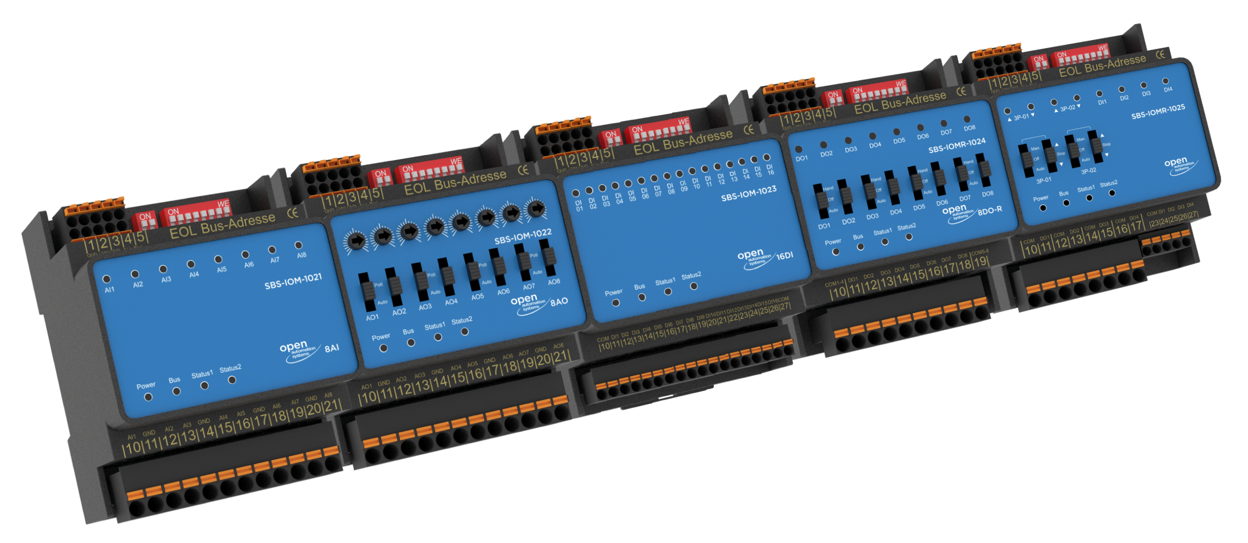
The SBS-IOM series consists of compact fieldbus modules with inputs and outputs for mounting on DIN rails, on the mounting plate in the control cabinet or electrical distributor or in the 19" rack, for mounting on the door.
Open, compact, comfortable
Sleek, intelligent and standardized is the series of SBS IOM fieldbus modules from OAS. This consists of compact fieldbus modules with inputs and outputs for analog and digital signals. The fieldbus modules acquire the signals of the building services equipment and pass them on to the controllers. Due to the standardized communication via Modbus RTU, no further gateways are required.
General Information
General Information
Sleek, intelligent and standardized is the series of SBS IOM fieldbus modules from OAS. This consists of compact fieldbus modules with inputs and outputs for analog and digital signals. The fieldbus modules acquire the signals of the building services equipment and pass them on to the controllers. Due to the standardized communication via Modbus RTU, no further gateways are required.
- Binary, digital and analogue signals are recorded, output and processed in the automation stations (Niagara platforms) at various points in the building and the building services systems via the SBS-IOM devices.
- The connection with the automation station takes place via a commercial RS 485 communication bus / MOD bus RTU
Secure: Local Override (LO)
Secure: Local Override (LO)
- The OAS-SBS-IOM series meets the requirements of the local override operation (LO) according to DIN EN ISO 16484 and VDI 3814.
- The manual and emergency operation for overriding the outputs of the automation station is carried out via switches and potentiometers as operating elements, which complies with DIN EN ISO 16484 and VDI 3814 for LO
- Status messages of the inputs and outputs are transmitted by LEDs.
- the function of the operating elements is also possible without bus communication (emergency operation)
- the LO control elements functionally replace conventional switches and signal lamps in conventional control cabinets and electrical distribution boards
DIN EN ISO 16484-3
DIN EN ISO 16484-3
The 4 module types of the basic series simply fulfill the task of opening up all physical data point types according to DIN EN ISO 16484-3:
SBS-IOM-1021 AI Input Function, Analog Measure 1.5 SBS-IOMR-1022 AO Output function, Analog Digits 1.2 SBS-IOM-1023 DI Input function, Binary Input Signaling 1.3 and Binary Input Counting 1.4 SBS-IOMR-1024 DO Output function, binary switching/setting 1.1 Standardized and open: Communication / MOD-BUS RTU
Standardized and open: Communication / MOD-BUS RTU
- MOD-Bus RTU is an open and globally proven standard that requires no investment in programming interfaces.
- The integration and communication with the automation station / Niagara platform takes place via a galvanically isolated RS 485 interface via / MOD bus RTU
- SBS IOM fieldbus modules work as MOD bus slaves on the MOD bus master (automation station).
- no further gateways required
OAS I/O WEB Module Configurator
OAS I/O WEB Module Configurator
Intelligent and comfortable: The OAS I/O WEB Module Configurator is available for Niagara 4 based automation platforms. Any configuration of module and I/O settings is done comfortably and semi-automated via the OAS I/O WEB Module Configurator using current standard web browsers.
OAS-SBS-IOM-1021
Analog inputs
8 analog inputs: 8 AI module (active/passive), 8 x status LED
The SBS analog input module for connection and signaling of up to eight analog values. Active signals (0 ... 10V) and various passive sensors (eg Pt1000, Ni1000) can be connected.
Part. -Nr. OAS-SBS-IOM-1021
As a registered OAS partner, we also provide you with Eplan data and wiring examples.
Technical Data
Technical Data
Power supply:
24 V AC or DC, connection via terminals
Resolution AI
10 Bit
Impedance
20 MΩ
Supply voltage
24 V AC or DC, +- 10%
Current consumption
8 AI max. 40 mA (DC), 80 mA (AC)
Power dissipation
8 AI max. 1.0 W (DC), 1.9 W (AC)
Counting puls (only digital inputs)
duration min. 10 ms, only for DC signals
Max. counter value (digital inputs)
65,535 (= 216-1)
Bus interface
RS485
Supported baud rates (Autobauding)
9,600 Baud, 19,200 Baud,
38,400 Baud, 57,600 BaudBus cycle time
individually depending on the baud rate and the number of data points that will be addressed
Memory
mPC internally
Max. number of write cycles
Configuration settings such as setting the LED colors, inverting the inputs, or upshift and downshift times are stored in the internal EEPROM and can be overwritten up to 100,000 times.
Protocol
MODBus rtu (RS485)
Inputs and outputs
see corresponding documentation of the respective modules
Environmental conditions
Operating temperature
0...50°C
Transport and storage temperature
0...70°C
Relative humidity
10...90%, non-condensing
Protection class
IP 20
Dimensions
H92 W72 D70 Weight 146
OAS-SBS-IOMR-1022
Analog outputs
8 analog outputs: 8 AO module (0..10V), 8 x Auto-Hand Poti
Analog output module for outputting eight 0 ... 10 V control signals. Using the switches and potentiometers, a local override operation (LO) can be realized.
Part. -Nr. OAS-SBS-IOMR-1022
As a registered OAS partner, we also provide you with Eplan data and wiring examples.
Technical Data
Technical Data
Power supply:
24 V AC or DC, connection via terminals
Capacity of the outputs
10 mA each (short circuit proof)
Resolution AO
10 Bit
Linearity error
< +/- 2%
Impedance
20 MΩ
Supply voltage
24 V AC or DC, +- 10%
Current consumption
max. 120 mA (DC), 160 mA (AC) with all analog outputs loaded
Power dissipation
max. 1.8 W (DC), 3.9 W (AC) with all analog outputs loaded
Counting puls (only digital inputs)
duration min. 10 ms,
Max. counter value (digital inputs)
65,535 (= 216-1)
Bus interface
RS485
Supported baud rates (Autobauding)
9,600 Baud, 19,200 Baud,
38,400 Baud, 57,600 BaudBus cycle time
individually depending on the baud rate and the number of data points that will be addressed
Memory
mPC internally
Max. number of write cycles
Configuration settings such as setting the LED colors, inverting the inputs, or upshift and downshift times are stored in the internal EEPROM and can be overwritten up to 100,000 times.
Protocol
MODBus rtu (RS485) Format 8 N 1
Inputs and outputs
see corresponding documentation of the respective modules
Environmental conditions
Operating temperature
0...50°C
Transport and storage temperature
0...70°C
Relative humidity
10...90%, non-condensing
Protection class
IP 20
Dimensions
H92 W72 D70 Weight 158
OAS-SBS-IOM-1023
Digital - binary input
16 digital - binary inputs: 16 DI module (24V), 16 x LED status red / green
Digital input module for connection and signaling of up to 16 messages. The digital inputs can be used as counters.
Part. -Nr. OAS-SBS-IOM-1023
As a registered OAS partner, we also provide you with Eplan data and wiring examples.
Technical Data
Technical Data
Power supply:
24 V AC or DC, connection via terminals
Capacity of the outputs
10 mA each (short circuit proof)
Resolution AO
10 Bit
Supply voltage
24 V AC or DC, +- 10%
Current consumption
max. 150 mA (DC), 220 mA (AC), all DIs loaded
Power dissipation
max. 3.6 W (DC), 5.3 W (AC), all DIs loaded
Counting puls (only digital inputs)
duration min. 10 ms,
Max. counter value (digital inputs)
65,535 (= 216-1)
Bus interface
RS485
Supported baud rates (Autobauding)
9,600 Baud, 19,200 Baud,
38,400 Baud, 57,600 BaudBus cycle time
individually depending on the baud rate and the number of data points that will be addressed
Memory
mPC internally
Max. number of write cycles
Configuration settings such as setting the LED colors, inverting the inputs, or upshift and downshift times are stored in the internal EEPROM and can be overwritten up to 100,000 times.
Protocol
MODBus rtu (RS485) Format 8 N 1
Inputs and outputs
see corresponding documentation of the respective modules
Environmental conditions
Operating temperature
0...50°C
Transport and storage temperature
0...70°C
Relative humidity
10...90%, non-condensing
Protection class
IP 20
Dimensions
H92 W72 D70 Weight 137
OAS-SBS-IOMR-1024
Digital outputs 3A
8 digital outputs 3A: 8 DO module relay outputs
Digital output module with relay outputs 230 V / 3 A in two groups, for control of eight drives or similar, LO realization via slide switch
Part. -Nr. OAS-SBS-IOMR-1024
As a registered OAS partner, we also provide you with Eplan data and wiring examples.
Technical Data
Technical Data
Power supply:
24 V AC or DC, connection via terminals
Specifications digital outputs:
Relay outputs (NO contact), max. 250 VAC)
Characteristics (Resistive Load):
Initial contact resistance
100mΩ (at 1A / 24 VDC)
Rated load
3 A at 250 VAC / 30 VDC
Max. switching voltage
277 VAC, 30 VDC
Max. switching capacity
830 VA (AC), 90 W (DC)
Endurance
1x10⁵ ops (Rated Load)
Inductive loads
should be avoided as far as possible, or be suppressed at the source, respectively.
Supply voltage
24 V AC or DC, +- 10%
Current consumption
typically 85 mA (DC), 220 mA (AC) with all relays activated
Power dissipation
max. 2.1 W (DC), 5.3 W (AC) with all outputs activated
Counting puls (only digital inputs)
duration min. 10 ms,
Max. counter value (digital inputs)
65,535 (= 216-1)
Bus interface
RS485
Supported baud rates (Autobauding)
9,600 Baud, 19,200 Baud,
38,400 Baud, 57,600 BaudBus cycle time
individually depending on the baud rate and the number of data points that will be addressed
Memory
mPC internally
Max. number of write cycles
Configuration settings such as setting the LED colors, inverting the inputs, or upshift and downshift times are stored in the internal EEPROM and can be overwritten up to 100,000 times.
Protocol
MODBus rtu (RS485) Format 8 N 1
Inputs and outputs
see corresponding documentation of the respective modules
Environmental conditions
Operating temperature
0...50°C
Transport and storage temperature
0...70°C
Relative humidity
10...90%, non-condensing
Protection class
IP 20
Dimensions
H92 W72 D70 Weight 171
OAS-SBS-IOMR-1025
3- point relay outputs
2x 3-point relay outputs: 2x 3-point DO-/ 4x DI module
Digital output module with 2 x 3-point relay outputs 230 V / 3 A in two groups, for controlling 2 OPEN - STOP - CLOSE actuators such as valves, flaps, shutters. Shutters or similar.
LVB realisation by means of slide switch. 2 x Auto-Off -Man (manual) switch, 2 x OPEN - STOP - CLOSE - switch
Parameters such as run times, emergency position, etc. can be set conveniently via the NIAGARA N4-based OAS I/O WEB module configurator. The parameters are also available as open Modbus registers.
Part No. -No. OAS-SBS-IOMR-1025
As a registered OAS partner, we also provide you with Eplan data and wiring examples.
Technical Data
Technical Data
Power supply:
24 V AC or DC, connection via terminals
Specifications digital outputs:
Relay outputs (NO contact), max. 250 VAC)
Characteristics (Resistive Load):
Initial contact resistance
100mΩ (at 1A / 24 VDC)
Rated load
3 A at 250 VAC / 30 VDC
Max. switching voltage
277 VAC, 30 VDC
Max. switching capacity
830 VA (AC), 90 W (DC)
Endurance
1x10⁵ ops (Rated Load)
Inductive loads
should be avoided as far as possible, or be suppressed at the source, respectively.
Supply voltage
24 V AC or DC, +- 10%
Current consumption
typically 68 mA (DC), 152 mA (AC) with all relay outputs activated
Power dissipation
max. 0.4 W (DC), 1.0 W (AC)
Counting puls (only digital inputs)
duration min. 10 ms,
Max. counter value (digital inputs)
65,535 (= 216-1)
Bus interface
RS485
Supported baud rates (Autobauding)
9,600 Baud, 19,200 Baud,
38,400 Baud, 57,600 BaudBus cycle time
individually depending on the baud rate and the number of data points that will be addressed
Memory
mPC internally
Max. number of write cycles
Configuration settings such as setting the LED colors, inverting the inputs, or upshift and downshift times are stored in the internal EEPROM and can be overwritten up to 100,000 times.
Protocol
MODBus rtu (RS485) Format 8 N 1
Inputs and outputs
see corresponding documentation of the respective modules
Environmental conditions
Operating temperature
0...50°C
Transport and storage temperature
0...70°C
Relative humidity
10...90%, non-condensing
Protection class
IP 20
Dimensions
H92 W72 D70 Weight 171

OAS-SBS-IOMR-1026
Digital outputs 16A
4 digital outputs 16A: 4 DO relay outputs each with LED and push button operation
Digital output module with bistable relay outputs 230 V / 16 A for controlling drives, flaps or four light circuits or similar. LO is realized by means of push buttons
Part. -Nr. OAS-SBS-IOMR-1026
As a registered OAS partner, we also provide you with Eplan data and wiring examples.
Download Data Sheet
Technical Data
Technical Data
Power supply:
24 V AC or DC, connection via terminals
Specifications digital outputs:
Relay outputs (NO contact), max. 250 VAC)
Characteristics (Resistive Load):
Initial contact resistance
100mΩ (at 1A / 24 VDC)
Minimum switching current
100mA (at min. 5 VDC)
Rated load
16 A at 250 VAC
Max. switching voltage
277 VAC
Max. switching capacity
4432 VA (AC)
Endurance
2.5x10⁴ ops (Rated Load)
Inductive loads
should be avoided as far as possible, or be suppressed at the source, respectively.
Supply voltage
24 V AC or DC, +- 10%
Current consumption
typically 14 mA (DC), 40 mA (AC)
Power dissipation
max. 0.4 W (DC), 1.0 W (AC)
Counting puls (only digital inputs)
duration min. 10 ms,
Max. counter value (digital inputs)
65,535 (= 216-1)
Bus interface
RS485
Supported baud rates (Autobauding)
9,600 Baud, 19,200 Baud,
38,400 Baud, 57,600 BaudBus cycle time
individually depending on the baud rate and the number of data points that will be addressed
Memory
mPC internally
Max. number of write cycles
Configuration settings such as setting the LED colors, inverting the inputs, or upshift and downshift times are stored in the internal EEPROM and can be overwritten up to 100,000 times.
Protocol
MODBus rtu (RS485) Format 8 N 1
Inputs and outputs
see corresponding documentation of the respective modules
Environmental conditions
Operating temperature
0...50°C
Transport and storage temperature
0...70°C
Relative humidity
10...90%, non-condensing
Protection class
IP 20
Dimensions
H92 W72 D70 Weight 171

OAS-SBS-IOMR-1031
Digital outputs 3A and digital inputs
4 digital outputs 3A and 4 digital inputs with LED: 4 DO- module relay outputs each with LED and auto off manual switch
Digital input / output module with four digital inputs and outputs each. For the control of four 1-stage drives or similar and for connection and signaling of up to four messages. Delay-free switching of the outputs without bus delay due to programmable logic functions. LO is realized by means of slide switch.
Part. -Nr. OAS-SBS-IOMR-1031
As a registered OAS partner, we also provide you with Eplan data and wiring examples.
Download Data Sheet
Technical Data
Technical Data
Power supply:
24 V AC or DC, connection via terminals
Specifications digital outputs:
Relay outputs (NO contact), max. 250 VAC)
Characteristics (Resistive Load):
Initial contact resistance
100mΩ (at 1A / 24 VDC)
Rated load
3 A at 250 VAC / 30 VDC
Max. switching voltage
277 VAC, 30 VDC
Max. switching capacity
830 VA (AC), 90 W (DC)
Endurance
1x10⁵ ops (Rated Load)
Inductive loads
should be avoided as far as possible, or be suppressed at the source, respectively.
Supply voltage
24 V AC or DC, +- 10%
Current consumption
typically 68 mA (DC), 152 mA (AC) with all relay outputs activated
Power dissipation
max. 0.4 W (DC), 1.0 W (AC)
Counting puls (only digital inputs)
duration min. 10 ms,
Max. counter value (digital inputs)
65,535 (= 216-1)
Bus interface
RS485
Supported baud rates (Autobauding)
9,600 Baud, 19,200 Baud,
38,400 Baud, 57,600 BaudBus cycle time
individually depending on the baud rate and the number of data points that will be addressed
Memory
mPC internally
Max. number of write cycles
Configuration settings such as setting the LED colors, inverting the inputs, or upshift and downshift times are stored in the internal EEPROM and can be overwritten up to 100,000 times.
Protocol
MODBus rtu (RS485) Format 8 N 1
Inputs and outputs
see corresponding documentation of the respective modules
Environmental conditions
Operating temperature
0...50°C
Transport and storage temperature
0...70°C
Relative humidity
10...90%, non-condensing
Protection class
IP 20
Dimensions
H92 W72 D70 Weight 171