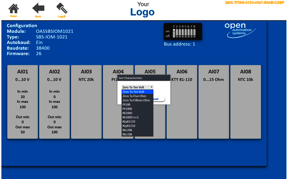
OAS I/O WEB Module Configurator
The OAS I/O WEB Module Configurator is based on the software module OASModbusUtilitiesAsync.
Simple, transparent, effective. The SBS I/O fieldbus modules enable the connection of digital or analog input and output values with the Modbus protocol. All necessary communication settings are made simply, transparently and effectively with the OAS I/O WEB module configurator.
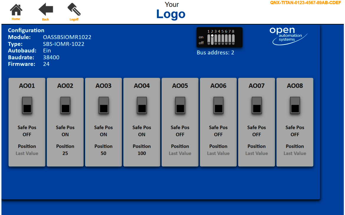
The OAS I/O WEB Module Configurator is used to configure communication with the controller in automatic mode via the RS 485 interface. The OAS I/O WEB Module Configurator is thus also a key to integrating the OAS I/O fieldbus modules into the Niagara platform. The configurable settings depend on the type of fieldbus module: digital or analog - according to the type of inputs and outputs, color change and LED color can be set for signaling active digital inputs or outputs, switching between normally open and normally closed, feedback protection, activation of safe position in case of malfunctions in the bus system, setting of analog characteristic curves, etc.
- any configuration of communication settings is conveniently and partially automated via the OAS I/O WEB Module Configurator on the Niagara automation platform.
- The configuration, monitoring and control of the inputs and outputs is implemented in automatic mode via the RS 485 interface.
OASModbusUtilitiesAsync
OASModbusUtilitiesAsync
The OAS I/O WEB Module Configurator is based on the software module OASModbusUtilitiesAsync.
This module is based on Tridium’s ModBusDriverAsync and enables easy commissioning and operation of the OAS Modbus modules. The OASModbusUtilitiesAsync can be accessed via Niagara Workbench or via web browser.
Software Version 1.0Article / Typ: OAS-MODBUS-UTILS-16







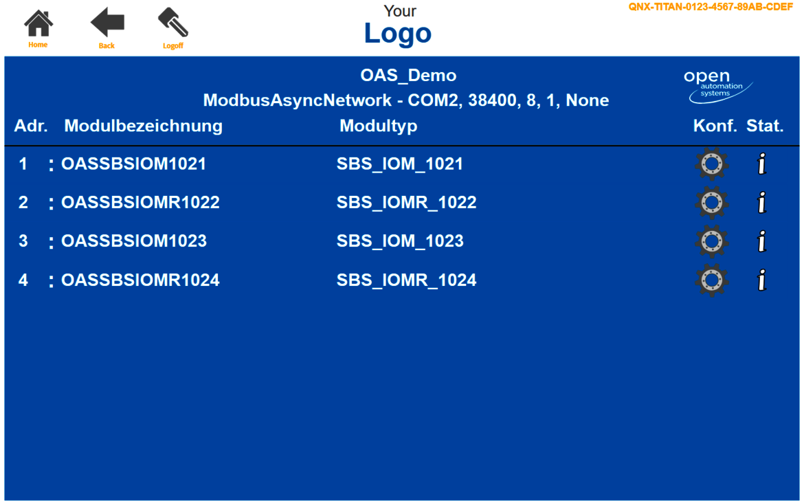


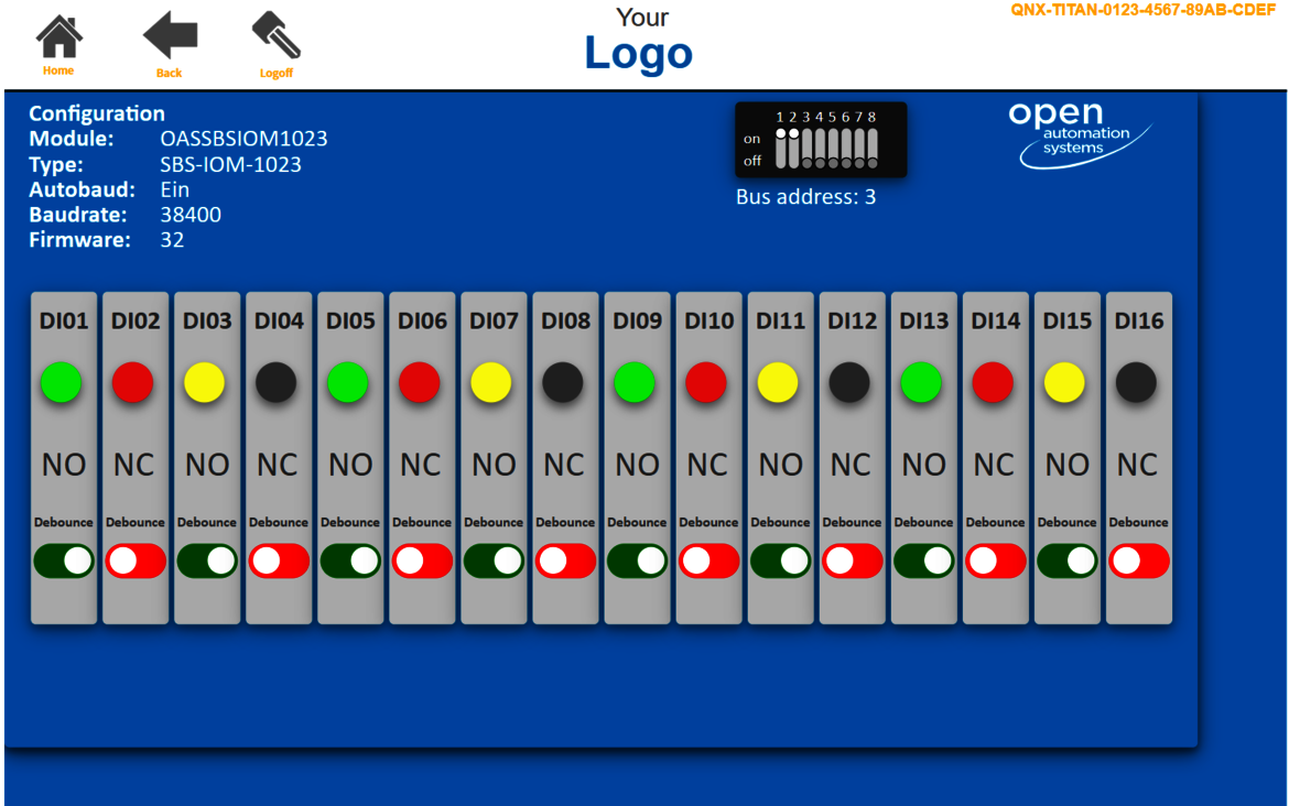
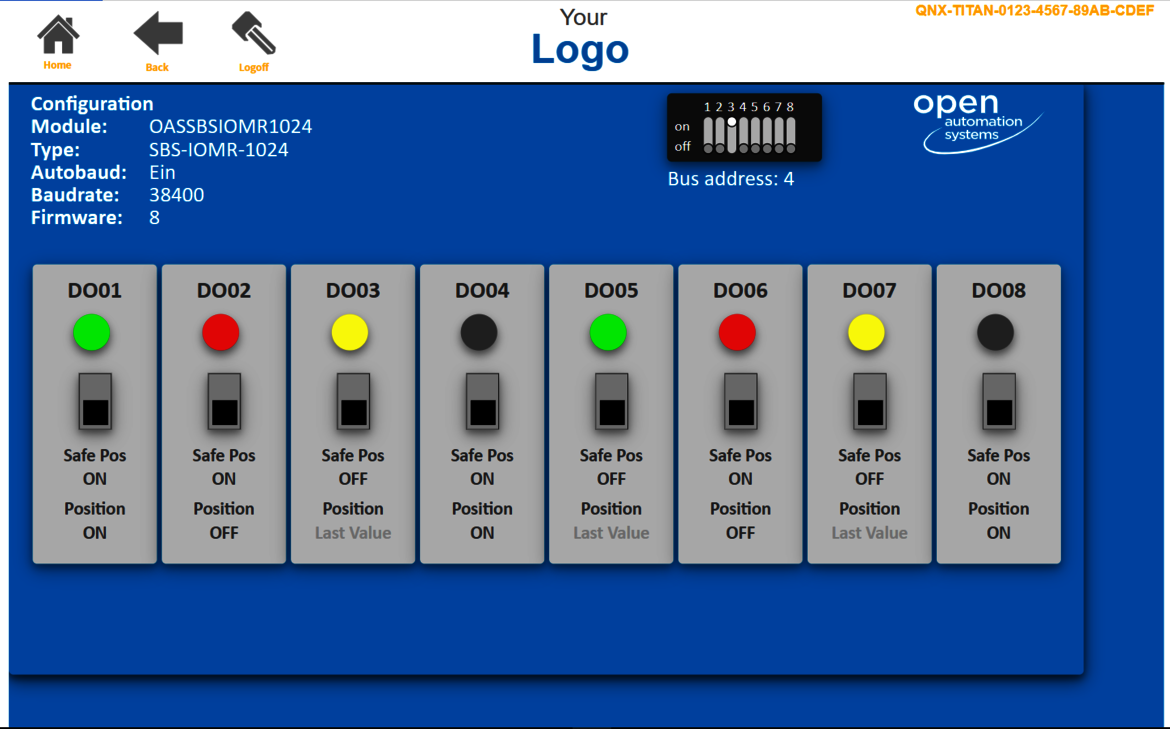
![[Translate to Englisch:] OAS I/O WEB Modul Konfigurator SBS IOM 1021 [Translate to Englisch:] OAS I/O WEB Modul Konfigurator SBS IOM 1021](/fileadmin/_processed_/e/f/csm_OAS-SBS-IOM1021_7ad3445cc2.png)
